Falsework Bracing
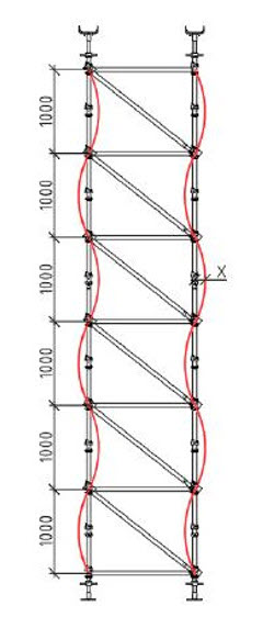
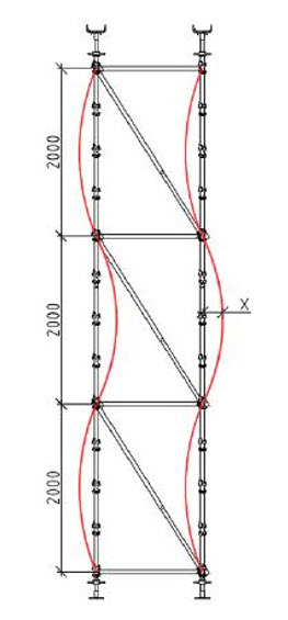
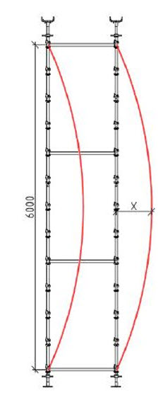
Falsework bracing is critical to the system taking the specified load, both during and after concrete placement. The bracing effectively stiffens the vertical elements of the falsework between the ledger lift heights. As you can see in Figure 1, the increase in lift height increases the bending of the leg, as denoted by the dimension X, which reduces the capacity. Bigger the bend, weaker the leg.
Bracing is not just for horizontal loads and ultimately provides what we term “reducing the effective length” of the vertical member, which simply means that the leg can be broken up into smaller segments between the horizontal supports, rather than a continuous member. This is shown in Figure 3, where it bends outwards from top to bottom jack regardless of the horizontal locations.


FIG. 1
FIG. 2
FIG. 3
It is a common misconception that after the pour you can remove the bracing. This is false and the falsework is still fully loaded until the jacks are wound down. The load from the concrete is not transferred to the columns and walls of the permanent structure until the falsework is removed. If you were to remove the bracing in the falsework, it would buckle and reassemble Figure 3 above.


FIG. 4
FIG. 5
It is a misconception that there are no horizontal loads in falsework if the slab is flat. This is false as there are dynamic actions taking part on the falsework that do create horizontal forces. This could be the line pump placed on the deck or wind load. The edge form also imparts a significant load on the falsework and is often forgotten about.
The capacity of scaffolding systems used as falseworks is overall governed by the horizontal connections of the ledgers to the standards, and the capacity of the diagonal bracing. Most systems are all 48.3mm tube of either 3.2mm or 4mm wall thickness and either grade 350MPa or 450MPa steel. Cuplok provides the greatest leg load capacity of any scaffold system used as falsework, as the horizontal connections are more rigid, followed by Ringlock and lastly Wedgelock.
Please note that this advice and the comments herein are general in nature. If ever in doubt, please seek advice from an engineer.
